
Hardware
(n) the physical parts of a device such as a computer or an AUV.


Our Enclosure -
We utilized a small waterproof cylindrical enclosure from Blue Robotics with a 100 mm diameter x 285 mm length with a half dome attached to one end of the enclosure that extends 73.5 mm at its apex. Two pressed fit o-rings make a watertight seal with the cylinder. To maximize the space that was available for our electronics, we prototyped several methods of mounting our electronics using 3D printed parts.
To create the foundation of our enclosure we designed a symmetrical cylindrical piece that ran the length of the enclosure. This cylindrical piece had slots in it that were used to slide flat panels with hardware components attached to both sides of the panel. In order for this to work we had to optimally position our hardware for ease of use when plugging in ethernet, power, or other connectors.
Cameras -
The slots in the cylindrical piece were also used as the base for our camera mount. We designed the camera mount in such a way that the camera points in a forward direction perfectly centered with regards to the enclosure. This allowed for the positioning of our forward-facing high resolution camera to be only 1 mm away from the apex of the half dome. In doing this we could avoid problems related to the curvature of the dome with respect to camera orientation
Feedthroughs -
An important feature of any waterproof enclosure is getting electrical wires through the enclosure without compromising the integrity of the watertight seal. Our feedthroughs include the six, three phase wires to our thrusters, a depth sensor, two battery connectors, and ethernet cable for communication with a ground station during testing. To save on cost we built several of our own custom feedthroughs. This included two battery power feedthroughs, and an ethernet feedthrough for the tether.
To accomplish this we used hollow aluminum o-ring feedthroughs from Blue Robotics. We then created a barrier in any wire passing through that feedthrough with a solid solder joint. Then followed by an epoxy potting of the wire in the feedthrough. This ensured that a nick in the shielding of the wire would not create a path for water to travel into our enclosure. We used a vacuum tester to verify our feedthroughs were watertight. Figure 5 is a picture of the process of making a homemade feedthrough.
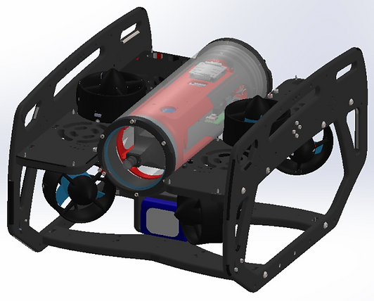
UUV Frame -
We leveraged an off-the-shelf enclosure and frame structure from Blue Robotics to speed the development process. After working through the mission requirements, we determined a six thruster propulsion design would be the best way to meet the 3 DOF motion requirement as well as the axial spin requirement.